The goal: separate a busy composition into readable heights
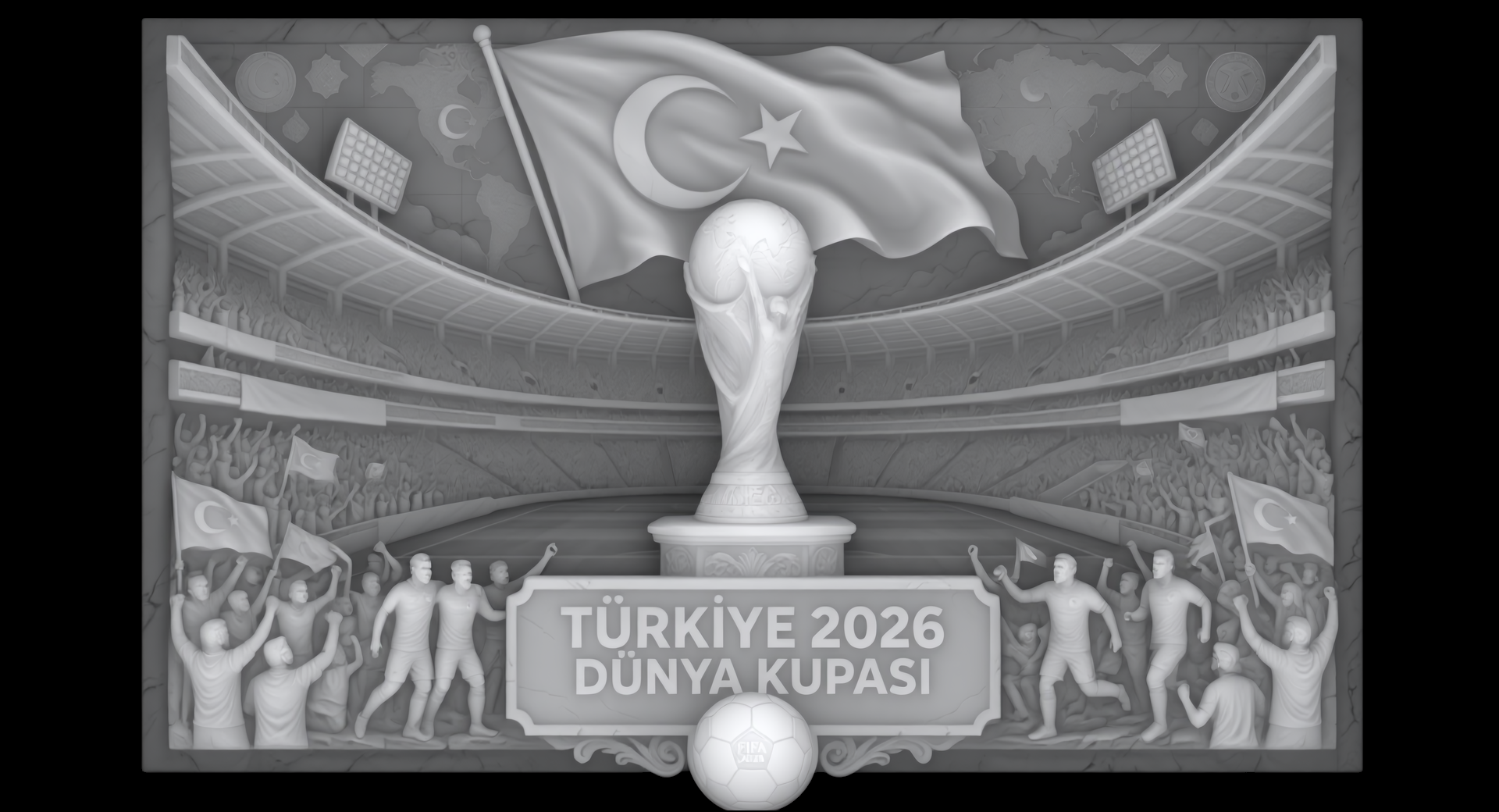
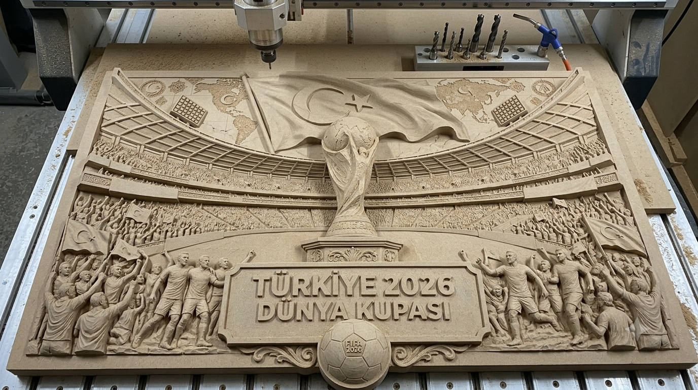
Sunar’s First Prize entry combines a flag, trophy, stadium, players and lettering in a wide relief. The submission provides the source artwork, a grayscale depth map and a photograph of the carving on a CNC router.
For CNC wood and MDF relief work, this is a useful composition to inspect: the large flag and trophy need to remain distinct from the stadium, while the lower figures, text and border need enough separation to read at the final size.

The creator’s recorded CNC setup
Sunar reports machining this piece from 30 mm thick raw MDF on a JHF Vista 1325 CNC router, using a tapered ball nose cutter with a 6 mm shank and a 3 mm tip.
The public description does not identify the CAM package, toolpath strategy, feed rate, spindle speed, stepover or actual relief height. The 30 mm figure describes the stock thickness; it is not a SculptOK Max Thickness setting or the depth of the cut.
| Item | Creator-reported detail |
|---|---|
| Stock | Raw MDF, 30 mm thick |
| Machine | JHF Vista 1325 CNC router |
| Cutter | Tapered ball nose, 6 mm shank and 3 mm tip |
| Result | Photographed relief on the machine bed |
SculptOK demonstration: inspect the surface before CAM
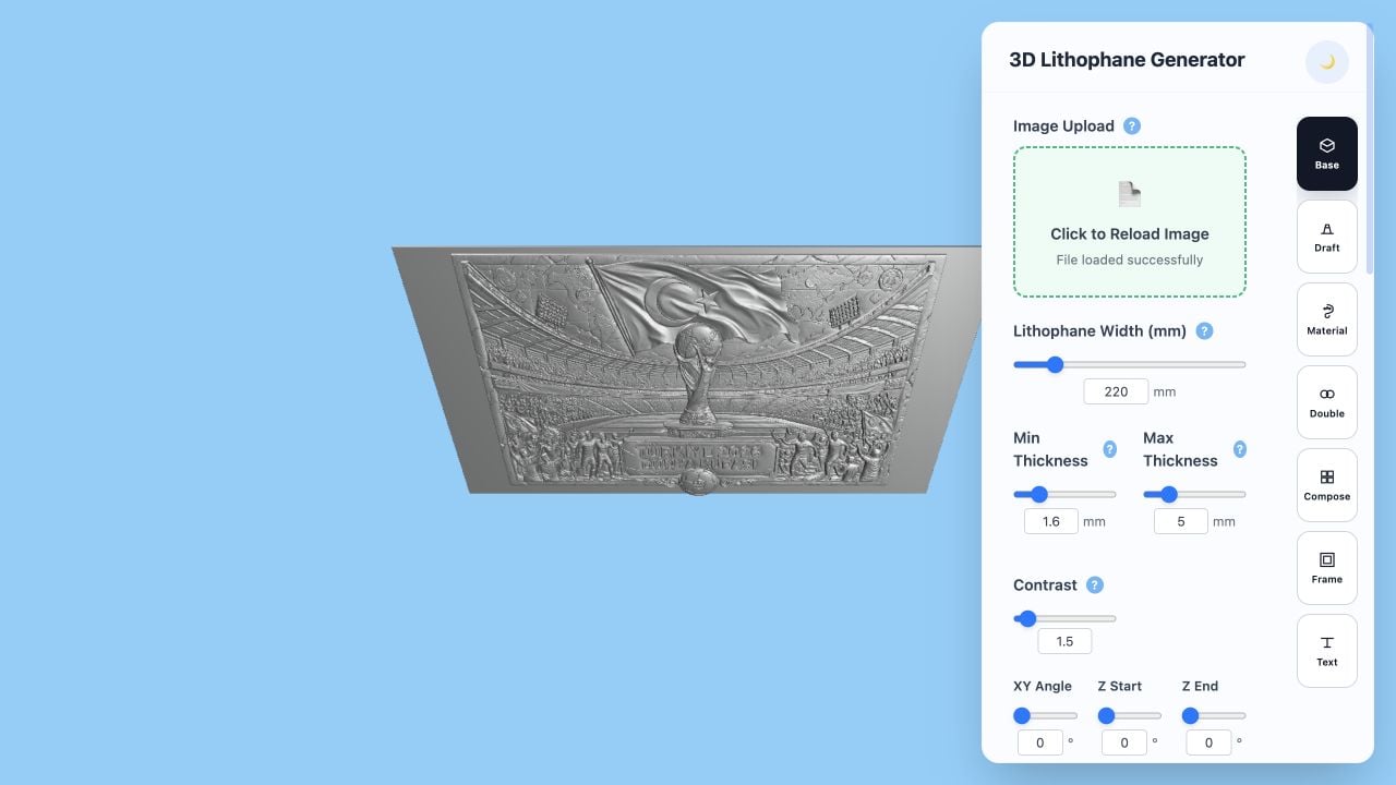
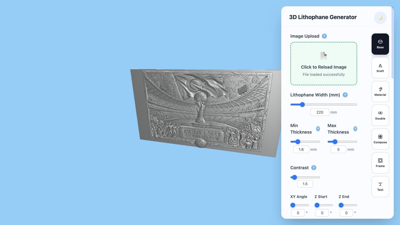
We loaded the original public depth PNG into the current 3D Lithophane Generator and inspected the surface from two angles. Check how the flag rises above the stadium, how the trophy separates from its background, and how the small figures and lettering read near the lower edge.
For this demonstration, Width is 220 mm, Min Thickness 1.6 mm, Max Thickness 5 mm and Contrast 1.5. Model Scaling is 100%, Invert Image is off, shape is Square, mode is Solid and Optimize Flat Back is on. The interface reports 1920 × 1040, 4,005,428 triangles and a model size of 219.9 × 5 × 119.2 mm.
These are SculptOK demonstration settings recorded on October 5, 2026. They are separate from Sunar’s 30 mm MDF stock and are not a cutting recipe. The preview used free controls; generation, VIP denoising and mesh export were not part of this demonstration.
Prepare your own wood or MDF relief for CAM
Start with a depth map whose subject and height direction you have inspected. Compare foreground and background in 3D; correct isolated defects or merged tones in the Depth Map Editor before preparing the manufacturing file.
Choose the input your CAM application supports. A height-map workflow may import the original grayscale image directly; a mesh workflow needs an exported relief such as STL or OBJ. Use the original depth file rather than the compressed WebP illustration on this page.
In CAM, confirm units, stock dimensions, relief height, remaining base thickness and where the model sits within the stock. Set the actual tool geometry, including tip size and taper, so the toolpath calculation represents the cutter you will use.
Prepare suitable roughing and finishing operations, then inspect the CAM simulation for uncut regions, tool reach and features too small for the cutter. Establish feeds, speeds and workholding for your own machine and material. The SculptOK preview helps inspect shape; the machine job is prepared and validated in CAM.
Common questions
Should I import a depth image or an STL into CAM?
Choose the route your CAM application supports. A depth image supplies height values for a height-map import; an STL supplies a mesh. Confirm scale, relief height and base thickness after import in either route.
How should I use the creator’s 30 mm MDF measurement?
Use it as a record of Sunar’s stock. For your own job, choose the stock and remaining base thickness, then fit the relief within that material in CAM. The demonstration’s 5 mm maximum thickness is a separate preview setting.
What should I check when small letters or figures are hard to carve?
First inspect whether the depth map separates those features. Then check the final physical size and the actual cutter geometry in CAM: details smaller than the cutter can reach may need a larger design, revised artwork or a different machining plan.